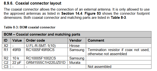
I’m trying to solder ufl socket to RaspBee. The instructions says "Additionally the terminating resistor must be removed from the antenna port. Assemble a 22 pF coupling capacitor and a 10 k resistor in parallel directly next to the U.FL connector. "
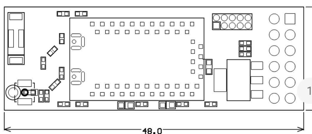
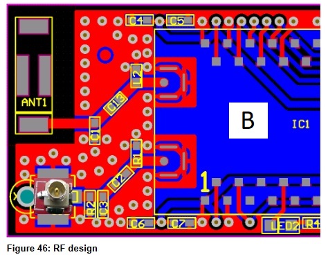
However, there are no diagrams to support this. Can someone please pin point these resistor and capacitor locations. I have attached the picture from the manual.
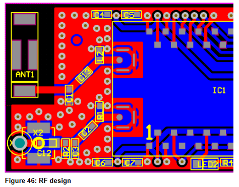
If I remember correctly the U.FL connector is next to the chip antenna, on the bottom left in the diagram.
I’ll ask our hardware devs for the locations of the caps and resistors.
Hi Manup,
I’m aware of ufl location at bottom left next to line antenna hole. Just the resistor and capacitors are not marked that needed to removed and replaced.
Thanks
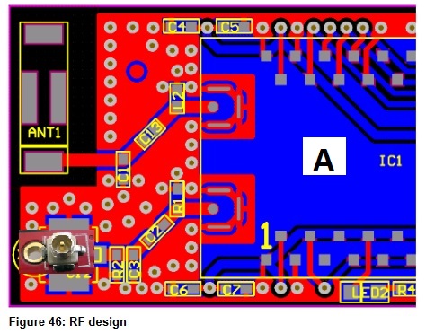
Thanks Chris for providing me the details. Just wanted to confirm the direction for soldering the Ufl socket.
Could you please confirm if it would be ‘A’ or ‘B’